Contact Us
Xi'an Camon Automatic Instrument Co.,Ltd
Address:1803Rm,buliding C, No.18, Dianzi First Road, Yanta District Xi'an China
Tel:+86-029-88243812
Fax:+86-029-88241170
Email:info@camoner.com
Post Code:710065
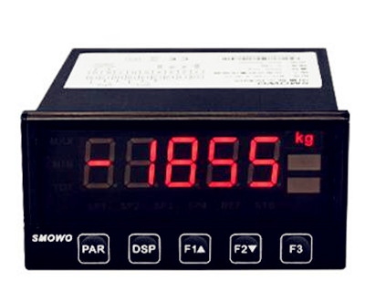
Input level transmitter
Wiring graph of D dimension instruments (72×72mm)
Note 1: Linear voltage signal of range below 500mV should be inputted from terminals 13 and 12, and signal of 0~5V and 1~5V should be inputted from terminals 11 and 12.
Note 2: 4~20mA linear current signal can be converted to 1~5V voltage signal by connecting a 250 ohm resistor and inputted from terminals 11 and 12.
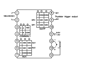
Note 3: S or S4 module can be installed in COMM slot for communication. If relay, TRIAC no contact switch, or SSR drive voltage output module is installed in COMM, it can be used as alarm output. If I2 module is installed in COMM and parameter “bAud” is set to 1, SV1 and SV2 can be switching by connecting a switch between terminals 3 and 4.
Previous: Magnetic column (magnetic column) level gauge
Next: No Information
Related Industry Knowledge
- Metal tube Float Variable Area Rota...
- Selecting The Right Thermometer Par...
- Selecting The Right Rotameter Part ...
- Electromagnetic Flow meter technic...
- Electromagnetic Flow meter Working...
- Selecting The Right Glass Rotameter...
- Selecting The Right Glass Rotameter...
- Magnetic column (magnetic column) l...
- Siemens SULTRAMAT 23 Gas Analyzer
- Selecting The Right Glass Rotameter...
- Metal tube flow meter Technican Par...
- Selecting The Right Glass Rotameter...
- Selecting the Right Glass Rotameter...
- Turbine flow meter Installation Cau...
- Use of pressure transmitter
- Electromagnetic Flow meter Installa...
- Rotameter Installation Notice
Related Products


 1803Rm,buliding C,No. 18,Dianzi first road,Yanta district Xi'an China
 +86-29-88243812
 +86-29-88241170


