Contact Us
Xi'an Camon Automatic Instrument Co.,Ltd
Address:1803Rm,buliding C, No.18, Dianzi First Road, Yanta District Xi'an China
Tel:+86-029-88243812
Fax:+86-029-88241170
Email:info@camoner.com
Post Code:710065
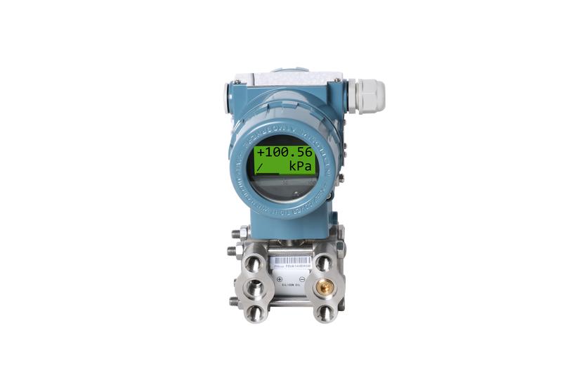
Differential Pressure Transmitter
The high performAnce differential pressure transmitter is suitable to measure liquid, gas,
or steam flow as well as liquid level, density and pressure. Its outputs a 4~20 mA DC
signal corresponding to the measured differential pressure. Its highly accurate and stable
sensor can also measure the static pressure which can be shown on the integral indicator
or remotely monitored via HART communications. Other key features include quick response,
remote set-up using communications, self-diagnostics and optional status output for pressure
high/low alarm.
FUNCTIONAL SPECIFICATIONS
Span/ Range Limits | kPa | inH2O | mbar | mmH2O | |
A | Span | 0.1~1 | 0.4~4 | 1~10 | 10~100 |
Range limits | -1~1 | -4~4 | -10~10 | -100~100 | |
B | Span | 0.2~6 | 0.8~24 | 2~60 | 20~600 |
Range limits | -6~0 | -24~24 | -60~60 | -600~600 | |
C | Span | 0.4~40 | 1.6~160 | 4~400 | 40~4000 |
Range limits | -40~40 | -160~160 | -400~400 | -4000~4000 | |
D | Span | 2.5~250 | 10~1000 | 25~2500 | 0.25~25mH2O |
Range limits | -250~250 | -1000~1000 | -2500~2500 | -25mH2O~25mH2O | |
F | Span | 30~3000 | 120~12000 | 0.3~30bar | 3-300mH2O |
Range limits | -500~3000 | -2000~12000 | -5~30bar | -5~300mH2O | |
PERFORmANCE SPECIFICATIONS
Reference Accuracy of Calibrated Span:
(includes terminal-based linearity, hysteresis, and repeatability)
±0.075%,±0.1% ,±0.25%,±0.5%
If TD>10(TD=URL/SPAN), ±(0.005×TD)%
The square root accuracy is 1.5 times of reference accuracy of calibrated span.
Ambient Temperature Effects
-20℃~65℃:±(0.075×TD+0.025)%×Span
Every 10℃ is ±0.04% ×Span (TD=1)
-40℃~-20℃ & 65℃~85℃:±(0.1×TD+0.025)%×Span
Static Pressure Effects
±(0.025%URL+0.05%Span)/10MPa
Over pressure Effects
±0.05%×Span /10MPa
Stability
±0.1%×Span /3 years
Power Supply Effects
±0.001% /10V (12~42V DC)
Zero Adjustment Limits
Zero can be fully elevated or suppressed, within the lower and upper range limits of the capsule.
External Zero Adjustment
External zero is continuously adjustable with 0.01% incremental resolution of span. Re-range can be done locally using the range setting switch.
Mounting Position Effects
Rotation in diaphragm plane has no effect. Tilting up to 90℃ will cause zero shift up to 0.4 kPa (40 mmH2O) which can be corrected by the zero adjustment.
Output
Two wire 4~20 mADC output with digital communications, linear or square root programmAble.
HART FSK protocol are superimposed on the 4~20 mADC signal. Output range: 3.9 mA to 20.5 mA.
Failure Alarm (the mode can be selected)
Low Mode (min): 3.7 mA
High Mode (mAx): 21 mA
No Mode (hold): Keep the effective value before the fault. Note: The standard setting of failure alarm is High Mode.
Response Time
The amplifier damping constant is 0.1 sec; The sensor damping constant is 0.1~1.6 sec, it depends on the range and range compression ratio. Amplifier damping time constant is adjustable from 0.1 to 60 sec by software and added to response time.
UpTime <15s
Ambient Temperature Limits
-40 to 85℃ / -20 to 65℃ with LCD display or fluorine rubber sealing
Storage and Transportation Temperature Limits
-50 to 85℃ / -40 to 85℃ with LCD display
Working Pressure Limits (Silicone oil)
mAximum working pressure:16MPa,25MPa,40MPa
Previous: Pressure transmitter Installation
Related Industry Knowledge
- High pressure glass rotameter
- CMDK(D)W SERIES METAL TUBE FLOWMETER
- Tubine flowmeter Technical paramete...
- Turbine flowmeter Wiring
- thermocouple working principle and ...
- Latvia customer paid the galss rota...
- Turbine flowmeter Caution Matters
- Bimetal indicating thermocouple
- Pressure transmitter Installation
- Explosion-proof Bimetallic Thermome...
- bimetal thermometer WS-40
- Oval Gear flowmeter Error Calculati...
- Oval gear flowmeter Installation an...
- WSSX-301 bimetal thermometer
- Electro-optical level meter
- Turbine flowmeter Installation
- Bi-thermometer brief introduction
- How to choose suitable tubine flowm...
- Turbine Flow meter Dimension
- Precious metal thermocouple
Related Products


 1803Rm,buliding C,No. 18,Dianzi first road,Yanta district Xi'an China
 +86-29-88243812
 +86-29-88241170


